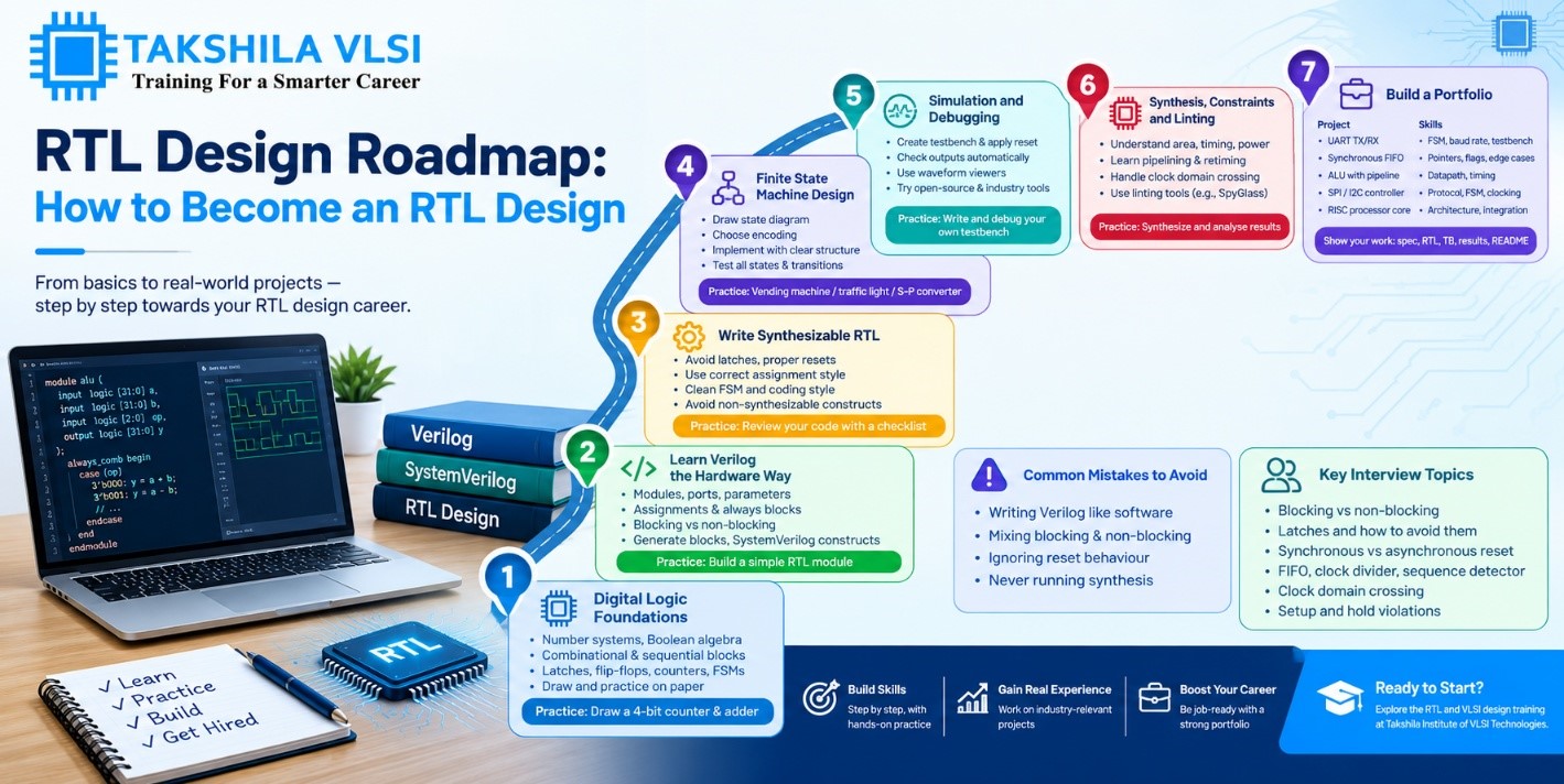
Every chip begins as a description of behaviour, and the person who writes that description is the RTL design engineer. RTL, short for Register Transfer Level, is where an idea about what a chip should do becomes code that tools can turn into real hardware.
If that sounds like the work you would enjoy, this RTL design roadmap will take you from first principles to a portfolio you can show an employer. It works as a Verilog RTL design tutorial in outline, and each section ends with something to practice.
What RTL Means in Practice
At the register transfer level you describe how data moves between registers on each clock edge and what logic transforms it along the way. You are not placing transistors or drawing wires. You are describing behaviour in a way that a synthesis tool can convert into logic gates.
That last phrase is the important one. Code that simulates correctly is not necessarily code that can be built. A large part of becoming an RTL engineer is learning the difference.
Step 1: Digital Logic Foundations
Strong basics make everything later feel natural. Study these until you can explain them without notes:
- Number systems, Boolean algebra and Karnaugh maps
- Combinational building blocks: multiplexers, decoders, encoders, adders
- Latches and flip-flops, and the idea of setup and hold time
- Counters, shift registers and registers with enables
- Mealy and Moore state machines
Practice: draw a 4-bit counter and an adder on paper before ever writing code. If you can sketch it, you can describe it.
Step 2: Learn Verilog the Hardware Way
Verilog is not a programming language in the usual sense. Each line describes hardware that exists at the same time, not instructions executed one after another. Keep this idea in mind and many beginner errors disappear.
- Modules, ports, parameters and instantiation
- Continuous assignments and always blocks
- Blocking (=) and non-blocking (<=) assignments, and when to use each
- Sensitivity lists and the difference between combinational and sequential blocks
- Generate blocks for repeated structures
Once you are comfortable, add SystemVerilog constructs for design such as logic, always_ff, always_comb and enumerated types. They make intent clearer and catch mistakes earlier.
Step 3: Write Synthesizable RTL
This step separates beginners from working engineers. Learn the habits that lead to clean, reliable hardware:
- Avoid accidental latches by assigning every output in every branch of combinational logic.
- Use non-blocking assignments for sequential logic and blocking ones for combinational logic.
- Reset carefully. Know when to use synchronous versus asynchronous resets, and how to release an asynchronous reset safely.
- Keep one clear style for FSMs, naming and formatting, so others can read your code.
- Avoid constructs that do not synthesize, such as delays and certain initial-block uses.
Most of these ideas are easy to state but take practice to apply under pressure. That is why reviewing your own code against a checklist is a helpful habit.
Step 4: Finite State Machine Design
FSMs control almost everything in hardware, from bus protocols to power sequencing. Learn to design them cleanly.
- Draw the state diagram and list the inputs, outputs and transitions.
- Choose an encoding: binary, one-hot or gray, and know the trade-offs.
- Write the code using a clear structure, such as a state register, next-state logic and output logic.
- Test every state and every transition, including illegal ones.
Practice: design a vending machine controller, a traffic light controller and a serial-to-parallel converter.
Step 5: Simulation and Debugging
Writing a testbench for your own RTL teaches you how designs fail. Create a clock, apply reset, drive inputs, and check outputs automatically instead of only looking at waveforms. Learn to use waveform viewers well. Many RTL bugs reveal themselves in a few clock cycles if you know where to look.
Open-source simulators such as Icarus Verilog and Verilator are good for learning. Industry tools like VCS, Xcelium and Questa add advanced debug features.
Step 6: Synthesis, Constraints and Linting
Synthesis turns your RTL into a netlist of gates. Learn what the tool reports: area, timing and power. Understand why a long combinational path limits your clock speed, and how pipelining can help.
Linting tools such as SpyGlass check your code against coding rules and catch issues like unconnected ports, width mismatches and unsafe clock-domain crossings before they reach later stages. Running lint early saves enormous time.
Concepts worth understanding
- Setup and hold, and how clock frequency affects timing
- Pipelining and retiming to improve speed
- Clock domain crossing and synchronizers
- Basic low-power ideas such as clock gating
Step 7: Build a Portfolio
| Project | Skills shown | Level |
| UART transmitter and receiver | FSMs, baud rate generation, testbench | Beginner |
| Synchronous FIFO | Pointers, flags, edge cases | Beginner |
| ALU with pipeline | Datapath design, timing awareness | Intermediate |
| SPI or I2C controller | Protocol handling, FSM, clocking | Intermediate |
| Simple RISC processor core | Architecture, control logic, integration | Advanced |
For each project, keep the specification, the RTL, the testbench, the simulation results and a short note on synthesis results. Put these in a repository and write a clear README.
Mistakes Beginners Make
- Writing Verilog like software and expecting sequential execution
- Mixing blocking and non-blocking assignments in the same block
- Ignoring reset behaviour until late in the project
- Never running synthesis, so they never learn what their code costs in hardware
Interview Topics for RTL Roles
- Blocking versus non-blocking assignments
- How latches are inferred and how to avoid them
- Synchronous versus asynchronous reset
- Design a FIFO, a clock divider or a sequence detector
- Clock domain crossing methods
- Setup and hold violations and ways to fix them
Ready to Begin?
RTL design is one of the most direct entry points into the chip industry. Learn the basics, write code with hardware in mind, build projects and keep reading your synthesis reports.
If you want structured guidance and lab practice, explore the RTL and VLSI design training at Takshila Institute of VLSI Technologies.